


..COMPONENTS USED..
1x circuit board
2x 1k ohms resistors
2x 560 ohms resistors
1x 5v (LED) yellow
1x 5v (LED) green
2x c547 B.J.T
plus jumper and power + earth wires
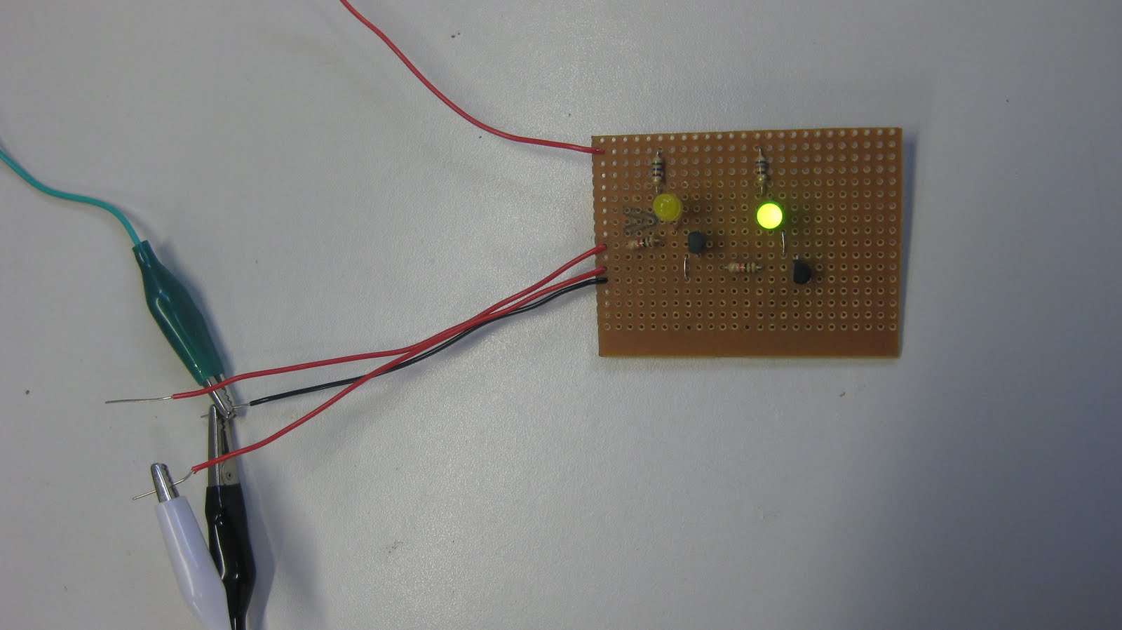
This circuit board i made is based on an injector circuit, using bi polar juntion transistors to amplify signal from ECU.
This particular circuit uses both a 5v and 12v input,.The resistors i used are a simple current flow control device.
A 12v current supply is sent to the collector of (bjt) and 5v to the base which in return lets current flow from the collector to emitter then to ground.
VD (voltage drop) was measured across all components with the following results..
R13 = 6.60v
R14 = 10.4v
R15 = 10.1v
R16 = 6.72v
LED (green) = 2.50v
LED (yellow) = 2.55v
V-CE = 0.05v
V-CE = 0.05v
V-BE = 0.88v
V-BE = 0.88v
These results were what was expected and this circuit board worked exactly how it was intended to.
No comments:
Post a Comment